Saturday, February 23, 2019

My Digital Lavalamp - or "The MkI Epilepsy Generator" - Part 3

Hola! You made it to Part 3, wherein I detail some of the discoveries, pitfalls and trials of implementing my standalone lava lamp software running in Raspbian.

Previously, on My Digital Lavalamp:

Part 1 - The inspiration and initial setup.
Part 2 - The physical build.

So, with the physical build complete [and having made my choices concerning buttons and lights], it was time to delve into setting up how the software driving the lamp worked ie: how it behaves when you turn it on and switch modes. I won't cover everything in absolute detail as that'd be boring, but I will link to the key places I found what I needed and discuss what I got working.

openprocessing.org
----------------------------------------------------------------------------

I discovered early in my processing sketch explorations that openprocessing.org was not only a cool site offering a live sketch programming facility, but that a large number of the sketches there were compatible with processing itself and would run simply by copying and pasting code into my own sketches. And thankfully the openprocessing.org Terms of Service regarding this are very friendly to creative endeavours:

"By submitting Content to OpenProcessing for inclusion on your account, you grant anyone Creative Commons license to reproduce, modify, adapt and publish the Content as defined by the license. If you delete Content, Wiredpieces Inc. will use reasonable efforts to remove it from the Website, but you acknowledge that caching or references to the Content may not be made immediately unavailable."

This meant I could openly reuse and adapt existing sketches and techniques there and modify them to run on my lamp. This led to many evenings of fun discoveries like this, and this which became modes I could incorporate into my lamp like such and so on. I already had a long list of things I wanted the lamp to do, but I was quickly adding new ideas I hadn't originally considered. WIN!

Some of the best modes remain modified versions of the test sketches that come with the fadeCandy codebase created by Micah Elizabeth Scott. I've yet to top those in terms of beauty, efficiency and speed.

Processing also ships with an excellent library browsing and installation tool that gives you instant access to a wide variety of tools to do everything from sound interaction to computational fluid dynamics:

 
Looking at some of these libraries I was inspired to create lavalamp modes that respond to changes in the weather, things that simulate hot fluids like a *real lavalamp*, as well as respond to sounds in the environment etc. There's even standalone voice-recognition libraries that I could use to get it to switch modes when I asked it to. So many possibilities.

I'll put all the sketches I have and some other bits and pieces up on gitHub for anyone who wants to build something like this or simply see what I did. It's time to talk about Raspbian.

Raspbian
----------------------------------------------------------------------------
The Raspberry Pi doesn't come with an operating system. Well, it can do, but you have to download and run it yourself from a SD card. You can run many different flavours of linux on a Raspberry Pi but the one I chose was Raspbian because it's the "official" operating system for the Pi and widely used.

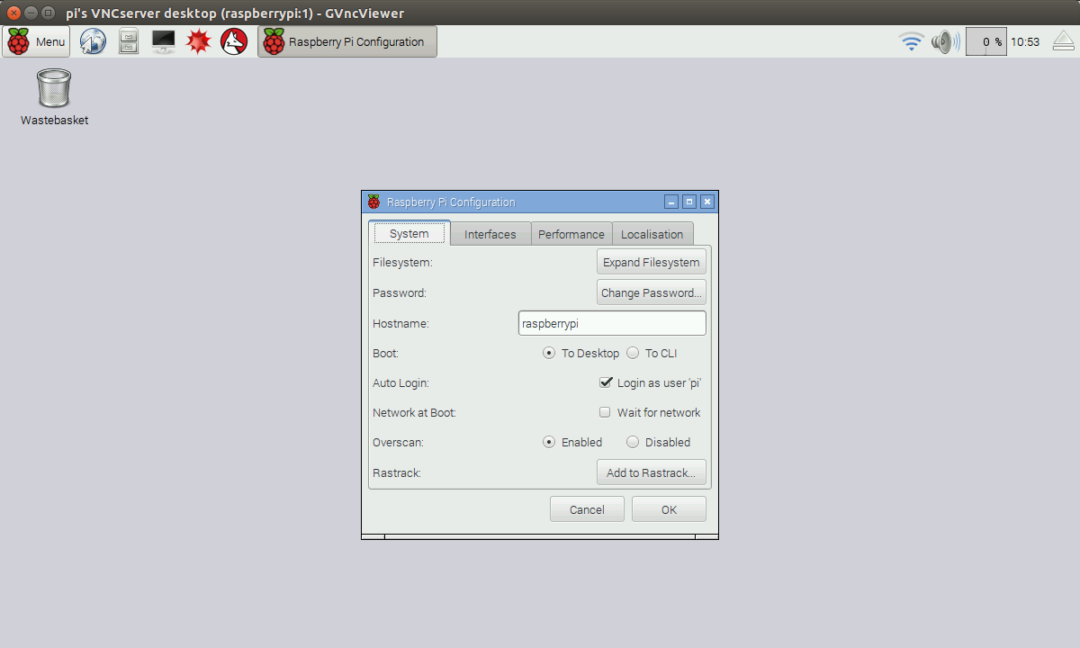
The first thing to do was download a copy of Raspian and flash it onto my SD card. I used an OSX utility called Etcher for this. In no time I'd booted the Raspberry Pi with everything connected and was welcomed by the Raspbian desktop and config utility.


From here setup was a breeze, with one exception. My mouse pointer was lagging and jittering all over the place. A quick search on Reddit revealed that I needed to add a line to the /boot/cmdline.txt config file. This is one of the many places in linux where you can tweak settings as the computer starts up. This issue is likely one that'll be fixed in later versions of Raspbian.

Add: 

usbhid.mousepoll=0

to /boot/cmdline.txt. There may be nothing else in that file if you're working with a fresh install where this might occur. I didn't encounter too many other issues apart from this with the exception of some wifi glitches that were fixed in a subsequent Raspbian release, so I won't cover them here.

Processing and Performance
----------------------------------------------------------------------------

With that done it was time to install and test the Processing performance playing through some of my existing sketches created on the Mac. In recent versions of Raspbian, Processing comes pre-installed, which is great. But, in case it doesn't, here's a link to info about where to find the ARM-specific version and how to install it: https://learn.adafruit.com/processing-on-the-raspberry-pi-and-pitft/processing

At this point, starting my Pi took about 10-15 seconds, after which it secured itself an IP address and presented itself on the network. I was able to connect to it in the OSX finder and simply drag and drop my sketches into a folder there and run them directly on the Pi by launching the pre-installed version of Processing. Which is when I first became aware of one of the chief differences between the Pi and a Mac Mini, namely CPU performance.


My Mac Mini [late 2014] is a Intel Core i5 running 2 CPU cores at 2.8GHz. So it's not exactly bleeding edge but it's got enough snot to chew through a lot of Processing draw calls, specially at the resolution I'd been prototyping my sketches at ie: 400x800 etc. Particle simulations run pretty smoothly, computational fluid dynamic solves run well enough to look like fluids etc. I was able to use Processing's additional 2D and 3D acceleration frameworks to speed up some effects too. I could afford to instance a transparent circular gradient .png file as a fire particles at high enough sizes and densities to look pretty cool.

WAT
The Raspberry Pi 3B+ however has a significantly smaller hardware capability. Although it's got a 1.4GHz Quad-Core ARM Cortex-A53 CPU, it's a very different CPU and draws a lot less power, creating a lot less heat and more importantly, simply doesn't crunch the same amount of Processing draw calls I was used to. I'd been spoilt by prototyping my lavalamp modes on the Mac Mini and was forced to make some economies and trade-offs to achieve the performance that I wanted in my lamp.

I'll go through what choices I made to combat this briefly and then we'll move onto the FadeCandy installation:

Compromise
----------------------------------------------------------------------------

Processing on ARM architectures doesn't currently support quite the same levels of 2D and 3D acceleration, so sketches that were using those things ran incredibly slowly [granted, I was only running one 3D acceleration sketch which I then abandoned]. But I was using 2D acceleration for drawing particles in some of the particles intensive sketches. This meant that I needed to make some changes like:
  • Disable the 2D draw support - depending on the sketch, it was adding maybe 25-30% performance gain over NOT using it. 
  • Lower the overall sketch resolution, which was ok because lets face it, technically speaking the sample resolution of the array was low to begin with. 8x15 LEDs is not exactly high-def. And 400x800px is a little rich. Sketches now became more like 100x200px, which as we know from the MegaPixel Wars in camera sensor resolutions, is a non-linear improvement. 
  • Lower the number of particles I was drawing. 
  • Change the particle itself from a transparent gradient .png file to a simple flat transparent circle() in the draw function and use other techniques to regain the softness I'd previously had. 
  • In other sketches where I was needing to draw lines or other shapes, simply lower the number of line() calls, make them fatter etc. 
  • If I needed to achieve an animated wipe or transition, I considered using a single large image and transforming it somehow, compared computing it's appearance otherwise [in fact, this is how I achieve my startup array test look]. 
With most sketches getting one or more of the adjustments listed above, I regained about 50% of the performance I used to have on the Mac Mini, which was good enough. Some of the computational fluid dynamic sketches required deeper digging to optimise for the Pi as they had more complicated compute functions as well as requiring drawing many particles.

I also found it helpful to specify a target frameRate() and work within that constraint until I'd achieved the speed and look I needed. By default I think Processing sketches will run as fast as they can - this may not be a good place to be! The look of your sketch may be affected by it's compute, so it's important to know what knobs to tweak to control appearance.

Even after shrinking and optimisation, my Simple Fire sketch can consume 83.2% CPU on the Mac Mini at 30fps.
Overall this phase was good. It forced me to economise and be efficient. It also made me work harder to achieve the look I was after and consider more difficult changes to some of the sketches I was working with.

FadeCandy
----------------------------------------------------------------------------
FadeCandy has a server/client architecture such that you can run the server on a main computer housed somewhere central, and then multiple small FadeCandy units can connect to that server to control LED strips where you need them. The server is very lightweight. All you really need to do is run it at startup and forget about it.

Here's an excellent guide for getting FadeCandy setup [on OSX] running a 8x8 array of addressable LEDs that also covers some wiring and power requirements: https://cdn-learn.adafruit.com/downloads/pdf/led-art-with-fadecandy.pdf

But if you want to run standalone on a Pi you need to download and make a version of FadeCandy that'll run on ARM etc - this legendary Adafruit guide has all these steps and more including running the FadeCandy server at startup - https://learn.adafruit.com/1500-neopixel-led-curtain-with-raspberry-pi-fadecandy/fadecandy-server-setup#

Note: in the guide I just mentioned, I stopped before creating the fcserver.json config file as I am simply running one FadeCandy board and didn't need to configure addressing the 3 boards used in that example.

The FadeCandy server page has some useful utilities for testing your LED strips etc and will also show you the serial number of the FadeCandy board you have once it's detected ie: plugged in via USB.

Processing talks FadeCandy
----------------------------------------------------------------------------

How does Processing interface with the FadeCandy server though? How do you even know what is being sent to your LED array from your sketch? Good question. This is where the OPC class comes in.

Shipping with the FadeCandy installation comes some example files created by Micah, that contain her Open Pixel Control java class for Processing. This is a suite of methods for telling the FadeCandy server where a LED [or multiple LEDs] are positioned relative to the sketch window. It has calls that allow you to mirror your physical LED array in Processing so you can accurately gauge how to achieve the visual effects you need. You then use calls like ledStrip() and ledGrid() to construct a sort of sample array whose points will query the colour of pixels under them and send that info per frame to the FadeCandy board over USB and then onto your actual array.

Here's what the OPC commands look like for my array:
opc = new OPC(this, "127.0.0.1", 7890);
opc.ledGrid(0, 15, 4, width*0.25, height/2, height/15, width/8, 4.712, true);
opc.ledGrid(64, 15, 4, width*0.75, height/2, height/15, width/8, 4.712, true);


The first ledGrid() command arranges and fills the first FadeCandy output channel of 64 LEDs and the second ledGrid() call fills the second channel with the remaining LEDs. The '4.712' is the rotation amount expressed in radians required to get the sample array mapped in a vertical orientation to match my LEDs wrapped around a cylinder.

Here's a couple of visual examples of the OPC dot sample array I'm talking about:


On the left, Micah's wavefronts example sketch at its original size, on the right, my optimised and shrunk particle fire effect.

You can see in these two sketches the result of the OPC library calls placing white dots in the sketch window that mimic the physical array of my lavalamp LED layout so I can see just where the colours of the sketch will be sampled and displayed externally. Of course, the white dots are not sampled [otherwise the LEDs would just display white!], just the colours underneath them.

So this means that you actually don't really need to run a sketch in a large window as there's a lot of wasted draw() that is not utilised. There's a lot of gaps between the dots. So, for an application like mine, I can make the sketch smaller and use a filtering function like filter(BLUR, 2) to handle smoothing the edges of moving shapes.

Startup, Shutdown and Sketch Changing
----------------------------------------------------------------------------
One of the realties of using a full Linux computer [or most others for that matter] as a lighting fixture is that you can't simple unplug it when you want some peace. Computers have file systems that may be busy in the middle of writing some important information when you cut the power, and this can corrupt the file system, potentially making your computer not even start up. I had little choice but to consider making a nice way to shut the Pi down when I wanted to turn it off. And without having a mouse, keyboard and monitor connected to it, how can this be done?

I needed a physical button. Well, two actually. One that could tell the Pi when to shutdown, and one to tell the Pi when to switch the current Processing sketch. Thankfully the Pi has GPIO header pins [general purpose input/output] that permit connecting many things up etc. This means with a little browsing at your local electronics store, a simple momentary switch can be used to send these signals.

GPIO pins on my Pi with two switches and a status LED connected.
After reading a bit I followed the instructions in this link to hook up my startup/shutdown button: https://howchoo.com/g/mwnlytk3zmm/how-to-add-a-power-button-to-your-raspberry-pi

This link also includes the instructions for getting this small python script to run when the system starts up automatically. This is really handy and I thought I could simply reuse this script launching facility to start the python script that would listen for my second button pushes to make the lavalamp sketch change. However, this was not to be - more on that shortly.

The setup in the link above requires making a small python script called listen-for-shutdown.py that uses a python GPIO library designed to sense voltage changes on GPIO pins and turn those into the system command that shuts down the Pi. You also make a shell script that will run this listening python script upon booting up the Pi. They're both small and lightweight - nice and simple.

When you do turn off the Raspberry Pi, it takes about 10 seconds to halt all processes and get into a low power state where it's safe to cut the main power. Before it does that it flashes the TxD LED that is soldered onto the main board along with some other lights. More info on those lights here. It'll flash that light 10 times quickly, after which it's safe to cut the power.

I chose to extend that status light to the outside of my Pi enclosure following another guide here:
https://howchoo.com/g/ytzjyzy4m2e/build-a-simple-raspberry-pi-led-power-status-indicator

Here you can see on the rear of my lamp base, the extended status LED and the startup/shutdown momentary switch.
I extended the last switch to the front of the housing as the sketch change switch. This was another identical momentary switch. Like I said, I thought I could simply use the same script launching system as the startup/shutdown switch, but no luck. For some reason that wouldn't work and it took some digging to discover why.

I wanted to have another python script running that would again just be listening for voltage changes on another set of the GPIO pins. This time though, the script would kill any running sketch-related processes, iterate through the string array of available paths to sketches, select the next logical one in the list and launch it. But every time I tried it, I couldn't even get it to launch the first sketch in the array. I tried about 4 different schemes for launching python scripts at startup, making the assumption that they were all failing. It was a little infuriating.

Actually what was failing was that all the script launch schemes I was using were not designed to launch interactive applications like Processing. They were designed to launch small utility scripts at different linux run-levels beneath the user-space and interactive levels where Processing could be initiated. That's why the listen-for-shutdown.py worked, because it wasn't ever trying to start a complicated graphical program, it only ever invoked the terminal shutdown command.

Once I understood this I found the information I needed. Here's where I read about that problem: https://www.raspberrypi.org/forums/viewtopic.php?f=91&t=219952

Then I had success. It was time to flesh out the main python script for managing the sketch list and which sketch played automatically on startup.

Speed and pre-compiling
----------------------------------------------------------------------------

If you've used Processing on a fast computer, it might seem pretty interactive when you launch a sketch from within Processing itself. But, trying this on the Pi, I found a much longer delay when launching, like more than 5 seconds in some instances, compared to my Mac Mini's 1-2 seconds. This would be a pretty laggy experience if you pushed the button on the front of the lamp and had to wait 5 seconds before something changed. I also didn't have a way to launch a Processing sketch from within the program interface via Python, so I would have had to write some master framework within one main sketch that contained all the sketches. That would become onerous to compile and add new modes to.

Processing offers a pre-compliation option where you can pack a sketch down into a standalone unix executable file compatible with your platform - in this case the Pi. When I tried this I discovered not only does it start up much faster on the Pi, but that I can control the launching of the sketch from the command line via Python. Success!

By using the good old 'top' command while a pre-compiled sketch is running, I could see at a glance that the main CPU hog is java and also that there were no other java processes currently occurring. This mean that to stop my sketch immediately I can simply execute the 'killall java' command to nuke it. This is a bit like using a hammer to squash a fly I realise, but as this Pi was simply devoted to being my lavalamp and shouldn't be running any other java processes, it's fine to use this method.


So, with the following pieces in place:
  1. A method to launch a python script after hardware boot,
  2. A means to detect hardware button input,
  3. A means of starting and stopping Processing sketches via the command line,
  4. A speedy and self-contained sketch format,
I had all the pieces in place to create a master python script to control switching between sketches:


It's pretty simple, and I'm sure someone reading it will find flaws and ways I could do it better. With most coding things there's always a better way.

Should you want to use what I've made you can find this script and all the sketches in the gitHub repo: https://github.com/JRButler/Digital-lava-lamp You're welcome to take it and modify it to suit your requirements etc.

Stretch Goals
----------------------------------------------------------------------------
Phew. That's a lot of stuff. Now that it's done, I've got a few stretch goals in mind. I reached my initial goals of making the lamp completely standalone and having switchable sketches triggered by a hardware button. While getting there it occurred to me that having a full linux computer running the lamp sitting on the local network meant that I could do some other tricks with it:

  • Have it serve a webpage over the local network so guests could control the lamp from their phone via animated gif buttons showing the different modes.
  • Employ a standalone voice recognition package to control the modes.
  • Run HomeBridge on the Pi to interface with some HomeKit devices via voice control.
  • Make more sketches that interact or reflect the status of other things ie: IFTTT integration.
  • Use my new found skills to build something like this - https://youtu.be/-SNIlKsPiwU

Anyway, that's about it! Thanks for reading.

-j


Sunday, January 20, 2019

My Digital Lavalamp - or "The MkI Epilepsy Generator" - Part 2

Ok, welcome back. Last we left off I'd managed to get LED array wired up, correctly oriented with the final vertical grid arrangement, and playing sketches while connected to my mac. It was time to get it wrapped around the central PVC cylinder and into the upside down vase on a temporary wooden base while I figured out what the diffuser solution would be.

If you haven't already seen it, here's Part 1.

I decided to rule evenly spaced lines along the length of the PVC tube as a guide to make sure that I placed the LED strips in the right spots. I really wanted them evenly distributed. I also thought that due to the fragility of the strips themselves, that I'd use 3M double sided tape pads instead of hot glue to stick them to the cylinder. The LEDs have the potential to heat up which might have caused the glue to fail.


I carved a temporary channel for the power and data wiring to pass out underneath the edge of the vase and just sat the glass instead of securing it. This allowed me to get a sense of the space I had to work with and what other considerations to make when building the final base.


Starting to look like something Tony Stark might have on his desk.
So this is a good spot to be in. I can prototype sketches to run and the array is in its final configuration pointed in the right direction. Now to test diffuser materials.

Diffusing
----------------------------------------------------------------------------

The first and simplest is a piece of paper. Which... is too hairy:


It does effectively hide the individual LEDs, but it's really not the thing to use. After a visit to the art supplies shop I came back with two different thin, frosted polypropylene materials to test:


You can see in the top row that the LEDs are far too individually visible with the first material. And even two sheets weren't enough to give the right effect. However the second material worked better, and after doubling it to two sheets thick it gave exactly what I wanted. None of the individual LEDs were really visible on their own and any patterns effectively blended nicely to produce smooth gradations of colour.

Testing it in the dark with a particle simulation yielded nice soft shadows and a warm campfire effect.


Shooting these clips with my iPhone, I began to confront the exposure issues that make shooting bright lights in dark places a bit tricky. It's really hard to get a sense of the right colours the lamp is capable of via digital cameras. What seems burnt out white at the bottom of the fire in the GIF above is actually really nice on the eyes. However, later I realised shooting under-exposed with a larger sensor would produce far better results. More on that later.

Standalone
------------------------------------------------------------------------------

So, it was about at this point I started considering a couple of things. 1: What is the final form of the base going to be, and 2: I wanted to put this somewhere else in the house and NOT have to have it connected to a computer via USB the whole time. This meant I needed to choose a small form-factor stand-alone computing platform that fits in the base I design, and can run the Fadecandy server plus compute the processing sketches that power the lamp.

Now, having chosen the Fadecandy board to control the lights, the choice of platform is reasonable [OSX, Windows, Raspberry Pi and Linux] but does NOT include Arduino. In fact one of the reasons  Fadecandy exists is to do serial computation at a rate that most Arduino boards cannot. So the only other readily available small form-factor platform is Raspberry Pi. It's also one I have a shot at doing more complicated coding and setup in due to it's embedded Python support.

There ARE more high-end small form-factor platforms out there ie take a look at https://www.hardkernel.com for more. AND those platforms offer potentially much more CPU power for computing sketches at a rate similar to my mac mini. But they cost more, need to be shipped internationally, require more cooling etc. Plus I could go buy a Raspberry Pi locally and start messing with it.

One more thing, the now famous and useful page I linked to in Part 1 - 1500 NeoPixel LED Curtain with Raspberry Pi and Fadecandy concludes with the following statement:

"Python and C both perform quite well on the Raspberry Pi. An expert programmer could make this a self-contained system, not reliant on a networked computer to drive the animation."
Now, that's what I needed to do. I wanted a fully standalone lamp with a button on the front to change sketches and maybe a knob to adjust a parameter in the currently playing mode etc? And the Raspberry Pi is available on the local network via wifi, so what about serving a webpage with animated GIF buttons for the different modes so guests can change it? Whoah, slow down there dude, you don't even have a Pi yet.

Ok, time to fix that.


Raspberry Pi Model 3 B+. NZ$60. A full quad-core linux computer you can fit in a pack of playing cards ... well, almost. It was pretty cool to unbox this, plug it into my monitor, give it a mouse and keyboard, an operating system [Raspian] on a SD card and have a computer up and running that comes with Minecraft pre-installed!? It certainly gave Jamie some ideas about building a lunchbox laptop with Retropie to take to school.

A couple of evenings tinkering around and I had the Raspberry Pi running my own lavalamp sketches completely standalone.

You can see here also a hardware button and a green status LED connected to the GPIO pins. More on that later. You can also see what a cluttered mess my desk is.
I'll cover the software side of this in the next post or two. But now that I had the Pi set up and knew how big it was I could start thinking about the base for the lamp.

Style choices
---------------------------------------------------------------------------------
The original ION lamp that inspired this whole thing was superbly minimalist. I was unable with my time and access to tools & materials to mimic their aluminium touch sensitive casing. I used an upside-down $14 vase anyway! I didn't want to do something too out of keeping. Looking around, I saw a variety of things that could work, maybe with some modifications etc


I wanted to keep a natural material feel to it, so maybe some wood? I really liked the white mesh of the light cover in the bottom right hand corner of the image above. That would provide a suitable amount of air flow for cooling as well as look relatively tidy? I kept looking and stumbled across this lamp in a local hardware store:
Oh hells yeah. A little steampunk maybe but, meh.
Plus it had a nice patch of solid material at the bottom that could provide a nice two-panel appearance. I brought with me the measurement of the diameter required to ensure the Raspberry Pi would fit inside laying flat, and it gave a little extra room which I'd need to accommodate the USB and power connections. Just how close that would come, I was soon to find out.

I was planning to run the Raspberry Pi in a headless fashion, so the HDMI and keyboard and mouse cables would not be required. I was connecting via wifi also, so no ethernet to consider. Just power, a USB-A or two for the Fadecandy and a mic perhaps?
Construction
---------------------------------------------------------------------------------
The cutting disc on the dremel made short work of the copper cylinder
I found a cheap cheese platter board at a local homewares shop that gave me some nice dark hardwood that made an excellent base to mount the Pi onto, and also provided the wood effect I wanted for the glass vase/cover to stand on. I cut two circles out and sanded the edges to provide a snug fit into the cylinder mesh.

So I underestimated the amount of room the USB-A plugs would require to fit inside the mesh cylinder and had to embark upon some shroud-stripping and smallification.
This might look a little dodgy but I'd really only exposed the ground wire and planned to heat shrink it anyways.
It fits, and it works. Phew!
I mounted the Pi up on some standoffs that'd give me some room to deal with cables and the Fadecandy board too. I countersunk the screws on the bottom so they wouldn't protrude. I planned to put some rubber feet on once it was complete.

While I was working through this phase I also made decisions about buttons and lights. I'll detail more about this in the software section. I needed one button to switch the sketch that was running and another to start up and shut down the Pi. The Raspberry Pi is a complete Linux computer and Linux file systems can be corrupted if they lose power - so you simply cannot pull the plug reliably. You MUST shut them down nicely or deal with losing everything.

I also wanted a status light that I could use at a glance to know if the lamp was on, or ready to be safely switched off etc. All these buttons and lights connect to the GPIO pins on the Pi but needed to be wired up and placed during this part of the build.

I decided to wire up both blue and green LED choices to see which I preferred. Although I liked the blue it was too piercing and I went with the green for a more old school look.

Cutting the button holes went easily enough with a combination of cutting and sanding discs on the dremel. One button on the front for switching sketches and one on the back for startup and shutdown.

I made the decision to go with two power cables to supply the lamp. This wasn't as neat as I hoped but I didn't feel brave enough to drive the Pi via the power supply I'd bought for the LEDs as their requirements at full-white might risk drawing too much juice and make the Pi brown-out. So I chose to live with running both the LED power cable AND the Pi 5.1v adapter supply together. They needed to go into the side of the base at the rear but I didn't want them rubbing on the rough copper cuts I made. So I lined the edge of this hole with a hose washer I found at the hardware store that was the right size.
It's not exactly strain-relief but it'll stop any wires from being cut. Also you can see where I slipped with the dremel and scratched the copper surface while cutting the power hole. D'oh!
I cut a groove into the top wood disc to give the vase something to sit into and not fall off. I had a plan to secure this even better once it was complete.

My first real look at the aesthetic direction.
I moved onto mounting the central PVC cylinder covered in lights to the top wooden plate. I needed something removable in case I needed to replace any LED strips or to fix busted solder connections etc. I used some of the remaining copper mesh and cut some bendable strips to make some right-angle brackets.
I drilled into some of the existing holes in the mesh to enlarge them just enough for the screws required.
Success. PVC tube attached.
Now it was time to get all that wiring below deck. No-one is going to see it thanks to the diffuser material inside the vase cover but heck, I'm a neat-freak. I needed to cut a hole through the wood and get the power and data wiring for the LEDs down to the Pi and Fadecandy etc.
It's ugly but it'll get cleaned up.
It's all stacking up nicely.
Diving back to the rest of the install for a mo, I took time to get the Fadecandy nestled happily underneath the Pi and shielded. I'd rationalised that the Pi would generate the most heat and as such bought two small heatsinks to place on the main CPU chipset. I didn't want the Fadecandy board above this and chose to seat it downstairs.

During my sketch investigations I found a small USB microphone on Amazon that just plugged in and worked in Linux. This meant that using a Processing library called Minim, I could modulate any parameter of a running sketch. So I could change the colour of the particles in my campfire sketch for example, just by monitoring sound in the environment. I decided to include this capability and make use of it later during the software phase.

The microphone was a little on the large side and had a flexible boom neck that I really didn't need. So I disassembled it and you can see the condenser unit sitting on top of the USB plug stack. It used to look like this:
I just need the mic and USB stuff really. Not the flexible neck or casing.
In taking it apart, I found it had a little logic board that I shrouded in transparent heat-shrink and placed underneath the Pi alongside the Fadecandy board - see the image above.
Cling to the wall status LED. Just hang in there little buddy.
The install was really coming together at this point. I still had to complete the pathing of the LED array power and data connections from the upper deck to the lower section, but in the meantime I installed the LED status light by simply bending the legs of the LED and foam taping it to the internal wall of the mesh cylinder. Not the neatest solution, but I didn't want to use glue or have to have another screw protruding through the mesh.
Upstairs/Downstairs
Ok. I knew at some point I was going to have to disassemble this thing and troubleshoot it for some reason. Who knows why. Something will go wrong at some point. I wanted to make it easy to do that by simply being able to disconnect the upper floor from the lower. Having messed about with flying small quadcopters recently I decided to use some XT-60 connectors because they were both reliable and they also happily conducted a LOT of power.
XT-60 for the win!
You can also see in the image above the capacitor I added to the incoming power connection to prevent any surges from frapping my LEDs.

Powering it up on the bench. You can see the green status LED as well as the Pi board lights through the mesh.
It's alive Stimpy!

And then with the cover on all that remained was to drill holes for the screws to keep the top wooden platform in place just poking out of the mesh. That's if for the build and install. From here on it's mostly software and adding new capabilities.

The next section will be all about the software side of things. I'll detail the tweaks and discoveries I made during my Raspbian setup as well as some Python for switching sketches based on pushing the front button etc. Also some Processing sketch discoveries. See you there.

Part 3 is here now.

-j

Thursday, December 13, 2018

My Digital Lavalamp - or "The MkI Epilepsy Generator" - Part 1

A three part series wherein I discuss the problems and solutions I encountered during the production of my own interactive LED lava lamp display:


PHOTOSENSITIVE WARNING: READ BEFORE WATCHING A very small percentage of individuals may experience epileptic seizures when exposed to certain light patterns or flashing lights. Exposure to certain patterns or backgrounds on a computer screen, may induce an epileptic seizure in these individuals. Certain conditions may induce previously undetected epileptic symptoms even in persons who have no history of prior seizures or epilepsy.


However, to get there from here, we'll have to go back a few steps...

Ion
-------------------------------------------------------------
I saw this product on a friend's desk at work: Ion - A Music Detecting Mood Light - Kickstarter.com and I wanted one.


But the Kickstarter campaign was long over, and the site it spawned to sell them post the campaign had shut down also. There were none on Ebay or anywhere else in stock I could find. I've owned lava lamps over the last 25 years and I really like them and this seemed like a really smart advancement. I was looking for a project that would force me to delve into addressable LEDs so I decided to make my own. What's better than a lava lamp that can be every lava lamp?

I started a massive Evernote file filled with questions about how to build it, what hardware to choose, what functions it could/should have etc. I consulted with friends and pooled ideas about different modes and what they thought might be cool etc. The original Ion lamp was capable of some pretty sublime colours, and also some cool interactive modes too:


I felt like I could see the the individual LEDs themselves and that I could improve on the resolution and offer a wider variety of modes including sound reaction, API connections to favourite services, IFTTT integration, voice recognition and, and ... and... well I'm still adding some of those now it's built.

One thing I haven't tried to replicate is the Ion's bluetooth connection to your phone. That's possible of course, but I had a lot to figure out and had better start with just controlling some lights first huh.

Fadecandy
-------------------------------------------------------------
I had to make a decision about how to control the LEDs. There are many ways to do this, but which was going to be the easiest and friendliest to my current coding capabilities? Plus, where there any which improved on the somewhat basic RGB output offered by off the shelf Arduino kits?

The answer is indeed yes thanks to Micah Elizabeth Scott and her Fadecandy hardware board. Micah Elizabeth Scott has been crafting displays for annual trips to the Burning Man festival amongst other art installations and interactive experiments. As she shows on her site, most normal LED controllers fall into a trough of sadness when it comes to blending hues together or displaying correct colouring as low light levels. She created the Fadecandy hardware to solve these issues.

She partnered with Adafruit to turn the Fadecandy board into a small and affordable form factor unit that can control a metric crap-tonne of LEDs for really, really big joy-filled displays.


Better yet, it can be controlled via USB from big computers and small, embeddable computers like the Raspberry Pi etc. And it interfaces directly with Processing, which I've already experimented with. Processing is a great platform to program generative art that can accept inputs including music, sound, sensors and other things. It's used by all sorts of creative people for interactive art installations, live music, large scale projections, small embedded pieces etc. Processing is also available for the Raspberry Pi, thus opening the door to my small scale needs.

Get some LEDs
-------------------------------------------------------------
Where better to get addressable LEDs than Adafruit themselves? Actually... shh, Amazon had the very same lights with waaaay cheaper shipping so after some rough calculations I ordered two 1 metre strips of 60 weatherproof NeoPixel RGB LEDs. I also ordered a 5-volt, 10 amp power switching power supply [to handle NZ's 240v mains power] and one Fadecandy board.

I decided that 8 vertical columns of 15 lights, wrapped around a cylinder should provide a suitable height and LED density to improve upon the Ion lamp resolution. I had to also figure out how to reproduce their diffuser solution as they talked on their page about their prototypes designed to deal with making the individual LEDs blend together into a whole. More on that later.

The first thing to do was to get the Fadecandy board powered and connected to a computer in order to test my LED strips to make sure there were no dead LEDs. They're relatively hardy but sometimes die during shipping.
Success! No dead NeoPixels.
I should mention at this point a note of gratitude to all the people on the internet who have written about their crazy projects and shared advice and tips on how to do stuff like this. This page in particular is excellent and offers a large amount of information for getting started.

Micah offers many example Processing sketches designed to run directly on Fadecandy once you're connected and have the Fadecandy server up and connected. Here's Jamie testing the mouse-driven interaction:


Another example sketch gives you the ability to transform a bitmap through the sample points that are sent to the Fadecandy board and thus onto the LEDS. Here's what a simple bitmap of fire can look like via that method:


It's quite effective. The colours are excellent and the brightness can be overwhelming at times. This is a powerful way to manipulate the light array that means you don't have to be an expert programmer, you can envision cool effects just using things you can make in Photoshop.

You can see the weird-ass bitmap I made in this example scrolling through the array sample points. These were meant to look like mini nukes.
With these simple examples working, and the creative power clearly accessible, it was time to form the complete array that will end up wrapping around the central cylinder in my lamp.

As detailed in the Adafruit NeoPixel Curtain example I spent some time mapping and designing the separation between the power requirements of the array and it's data inputs. Each Fadecandy board offers 8 data outputs that can drive 64 NeoPixel LEDs each. I planned to drive 120 LEDs split into two strips. It was easy enough to simply drive each strip with a channel from the Fadecandy and not be too concerned that I wasn't using all the bandwidth of each channel. This did make for some funky OPC mapping that we'll get to soon.

The next step involved soldering, which I can do but have never been great at. Nothing better than a reason to practise.

Here's the array layout with my hand drawn power and data connections. You can see the arrows indicating the direction of the serial data that tells each LED what colour to display. I had to wire and solder all the missing parts at the end to complete the flow:


Enter the Vase
-------------------------------------------------------------
I should mention at this point that I'd decided on the length of the strips according to the final form I intended to deploy the strips into. I wanted to mimic the Ion lamp styling and presumptuously assumed a local homeware shop [Briscoes] would simply have cylindrical glass vases that might suit the task. They did! Here's a pic of the vase, upside down on a temporary wooden plate with a central core of PVC tube from the hardware shop:


My plan was to complete the wiring with the array laid out flat, then transfer it to the PVC tube and resolve the rest of the wiring loom issues as I went. I also gambled on being able to solve the diffuser issue down the line too as I could simply remove the vase and line it with some acrylic later once the array was working correctly. I still had no concept of the final installed form at this point, much less what small single board computer to run it off. I thought who cares if I only ever have it running connected to my computer while I'm dorking about?

After a busy few hours of soldering and insulating, I had the strips connected and ready to test. Although a few of my solder joins failed [embarrassedFace.jpg] thankfully I'd not made any short circuits and my array successfully lit up.


Having got this far, I could not resist testing some more complicated array graphics and modes.

Yeah I know, my desk is a mess.
I quickly ran into some issues to do with how I'd chosen to lay out my array and how the Fadecandy board and Processing saw things working out.

Radians, and assumptions
-------------------------------------------------------------
As any Fadecandy enthusiast will know, a visit to the Fadecandy google group page will show that multiple people want to layout their LED arrays in different and sometimes challenging ways.

I'd made the assumption during my wiring stage that my horizontal layout could simply be rotated in the Processing sketch or OPC layer to be vertically oriented and wrapped around a cylinder. Here's an example of the indexing of the zigzag array I'd followed [this example matches an 8x8 NeoPixel grid but the result is similar for a 15x8 grid - just longer on one side]:


You can see that the data input for the array enters on the top left at the 0 index, continues along the top to the right end where it zigs [or zags?] down onto the next row, this time in reverse order to the left hand end and then zigs again onto the next row, this time in the correct order etc. And on until the end of the layout.

It's vitally important that the Fadecandy understands the intention of this layout so that it knows how to take the sample points in the processing sketch and convert the resulting pixel colour information into the correct spatial information when it's sent in serial down the data pin connection of the LED strip.

My problem was that I actually required a layout more like the following image and that, being the VFX artist I am, I could simply specify a 90 degree rotation to achieve the correct result:


I needed this layout so that all my input power and data wiring would be near the bottom of the layout and that the longest dimension [not represented properly here] would be vertical, to match the height of my lava lamp physical orientation once the array was wrapped around the PVC cylinder.

Although I had success with running sketches on the array as I'd wired it horizontally, if I simply rotated my LEDs 90 degrees it meant that a graphic element running in the Processing sketch from top left to top right would run from bottom left to top left on the array. Gadzooks. This throws a spanner in the works of some of my ideas for things based on physics, like sketches that use a gravity direction meant to mimic the real world.

I had no clear place in the Processing sketch to rotate the output, and it was not immediately obvious where else I could effect this?

It's beautiful. But it's horizontal. This will not do.
After some forum diving and Fadecandy google group spelunking, I hit on this thread in particular about a person who had a non-standard NeoPixel layout who needed to perform a similar rotation-based remapping operation. They used a rotation value specified in radians to get the correct orientation in conjunction with some other value swapping kung-fu.

If you get on down to building a Fadecandy project yourself you're going to run into the problem of which OPC library call to use to map your Processing sketch out to your array. I settled on using two opc.ledGrid calls, the syntax for which looks like the following:

opc.ledGrid( index, stripLength, numStrips, x, y, ledSpacing, stripSpacing, angle, zigzag, flip )
After some head scratching and monkeying around, I successfully remapped my sketch layouts out to my array via the two Fadecandy channels I was using with the following commands:

opc.ledGrid( 0, 15, 4, width*0.25, height/2, height/15, width/8, 4.712, true )
opc.ledGrid( 64, 15, 4, width*0.75, height/2, height/15, width/8, 4.712, true )

I've highlighted in the lines above the radian specification for the rotation required. This worked! And it now gave me sketch output in Processing that was oriented correctly for the cylinder arrangement.

Success! Now I can move onto the physical installation, knowing that gravity points down. Duh.
With this problem solved I was pretty certain that I could progress onto the next stages of the design - the physical form factor, and also start considering some other issues like, how can I add a button to the front of the lamp to change the sketch? What small computer could it run on?

While I considered those things, I also spent some time making sketches in Processing to run on the array and experimented with designs from https://www.openprocessing.org where a great many people share their ideas with the world. The terms at OpenProcessing.org specify that any work uploaded or created on their site falls under a Creative Commons license unless specified otherwise. I've found many sketches there that simply run in Processing locally quite well. They require tuning and optimising to run on the lava lamp array but this is quite fun.

So, that's it for Part 1. In Part 2 I'll discuss the computer platform choice and show the housing construction. In Part 3 I'll detail the steps and software I created to deploy what I'd built into a standalone unit with wifi where I can add new modes wirelessly. And a stretch goal...


Part 2 this way...

-j